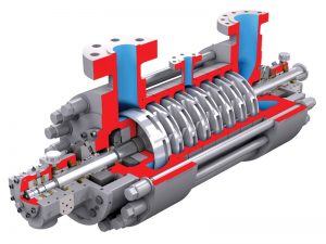
Diffusers are stationary elements mounted in the compressor casing. There is one diffuser downstream of each
impeller. The diffuser converts velocity to pressure. Each diffuser is contained in a removable section of the casing called a diaphragm. Each diaphragm also has a passage that directs the gas to the suction of the next impeller. Each impeller and diffuser assembly is a stage of compression.
The shaft is supported at both ends by journal bearings. These are normally tilt-pad type bearings. Another bearing mounted on the shaft is a thrust bearing. The thrust bearing absorbs the axial or horizontal force generated by unequal pressures on the impellers. A balance piston mounted on the shaft neutralizes as much thrust as possible. This neutralization is accomplished by connecting a high-pressure zone to one side of the piston and a low- pressure zone to the other side of the piston. The residual thrust is absorbed by the thrust bearing on the end of the shaft. This value changes as a function of compressor differential pressure (Discharge-Suction).
Case seals are located at each place where a shaft enters the casing. Normally there are two seals for each casing. These seals usually contain pressurized oil to prevent the leakage of any gas from the inside of the compressor to the atmosphere. However, gas seals can also be used. These seals direct small amounts of leakage gas to flare (1 SCFM or less).
Internally, labyrinth seals minimize recirculation of gas from high-pressure zones to lower pressure zones.
The casing of a centrifugal compressor is divided, or split, into halves that are held together by bolts. This division permits access to the internal parts without disconnecting the suction or discharge piping if the nozzles are mounted on the lower half of the casing. The casing may be split horizontally into an upper and lower half or it may be split vertically so that one end of the compressor is removable. The vertical split is called a barrel compressor.
Intercooling
Frequently, a compressor service requires two or more casings. The gas is cooled in between casings. The reasons for intercooling can be any of the following:
• To avoid exceeding a maximum temperature limit set by the mechanical parts or by the seal oil.
• To reduce power requirements.
• The additional casings are necessary because many impellers are required. Intercooling is then convenient.
For calculations, each casing is treated as a separate compressor. Each casing is often referred to as a stage.
This stage is a process stage and should not be confused with the impeller/diffuser assembly discussed earlier.
See Figure below:
Sidestreams
Sometimes additional gas is added to a compressor casing between wheels (impellers). This is common practice with refrigeration compressors, where some gas is available at higher pressure. This gas is called a sidestream. Sidestreams may also be taken out before discharge pressure is reached.
These sidestreams divide the compressor into sections. Each section must be calculated as a separate compressor and has its own performance curve.
PERFORMANCE CURVES
Performance curves contain the following information:
• Head versus flow characteristic at several speeds
• Horsepower versus flow rate and speed
• The surge limit
Manufacturers plot performance curves in several ways. The x axis may show actual cubic feet per hour or
volume flow at standard conditions. The y axis may show polytropic head, pressure ratio for a particular gas, or
discharge pressure for a particular gas and a particular suction pressure. The most useful parameters on a
performance curve are head and efficiency vs. actual flow since they are relatively unaffected by gas
composition or inlet temperature changes.
Figure below shows a typical manufacturer’s performance curve for a specific compressor.
Remember that the compressor always produces the same polytropic head at a given speed and actual volume flow. If the gas composition or the suction temperature changes, then the pressure ratio and the discharge pressure will change. If the molecular weight of the gas increases, the pressure ratio will increase. The horsepower required will also increase.
The polytropic efficiency for a machine is also constant at a given actual volume flow rate and speed.
Manufacturer’s performance curves are used for the following purposes.
• To determine whether a particular operation will be within the limits of the machine. The curve will tell you if an operating condition such as flow, gas composition, suction pressure or discharge pressure is feasible.
• To determine the correct speed for a set of process conditions such as suction ACFM and head.
• To determine the brake horsepower required for an operation, so that you can see if the driver will have enough power.
• To compare actual operating head and efficiency with the predicted values. This determines whether the machine is performing normally or whether it needs maintenance.
* This assumption is valid for gas density changes of 20%. Greater changes affect the head produced. In these instances, a new performance must be supplied by the original equipment manufacturer (OEM).
SURGE
One important characteristic of a centrifugal compressor is its surge point. Surge is a condition at which flow
through the compressor becomes unstable. This condition must be avoided to prevent damage to the machine.
Surge occurs as follows: As the system resistance increases, a centrifugal compressor reacts by backing up on
its curve. That is, the flow decreases so that the head produced can rise to match the system demand. When the
highest point on the compressor curve is reached, the compressor cannot increase the discharge pressure further.
At this point, the system discharge pressure is higher than the maximum possible discharge pressure of the
compressor. The flow in the impellers becomes unstable and reverses, causing the discharge pressure to
collapse. After a few seconds forward flow resumes. The discharge pressure rises again and the cycle repeats
every few seconds.
Surge occurs at a predictable flow rate. This flow rate is shown on the manufacturer’s curve. In practice,
controls are provided to keep the actual flow rate above this minimum value.
Read Also Surge Control in Centrifugal Compressors
EFFECTS OF SURGE
It is normal practice to take careful precautions to prevent surge. Surge disrupts the process and it can damage
the compressor. As a result of the reversing flow, the direction of shaft thrust reverses. The temperature rises
because the gas is internally recycled and recompressed. Compressor vibration and speed fluctuations are quite
common. The reversing axial motion, high temperatures, and fluctuating pressure can also damage the compressor seals. In a severe case, failure of the seal or the thrust bearing, or even the impellers, can occur. External piping can also be damaged. A check valve is normally installed at the discharge of a centrifugal compressor. During surge, this check valve can slam shut many times. This causes loud noise, pipe vibrations, and possible leaks at piping flanges.
Antisurge Control
In addition to matching process flow to compressor capacity, the flow rate must be kept higher than the surge point. This higher flow rate is accomplished by recycling a portion of the compressor discharge flow back to the suction vessel. This practice keeps the flow through the compressor above the minimum flow required to keep the compressor out of surge. A flow transmitter is located in the discharge line from the compressor. A signal from this flow transmitter controls the control valve in the compressor recycle line. If the discharge flow falls below the minimum safe value, the recycle valve opens and maintains the minimum flow rate. The circuit must be arranged so that the recycle flow always flows through a cooler. Otherwise, the recycling gas would continue to be heated and exceed the temperature limits of the compressor.
In many installations a small computer is added to the controls. The computer calculates the actual surge flow at any moment. This flow rate is not a constant value, but can change with process conditions and gas composition.
Another requirement is that the recycle controller must respond quickly when the flow drops below the minimum. Normal flow controllers experience reset windup. With reset windup, it can take up to one minute before the control valve opens. A compressor recycle controller must have special features to eliminate reset windup. In addition, the instrumentation used must have adequate accuracy and the control valve must open quickly (1-2 seconds).
STONEWALL
Another phenomenon encountered in centrifugal compressors is stonewall. As the flow rate through the compressor increases beyond the design value, the amount of head developed decreases. The greater the flow rate, the faster the developed head decreases. At a certain point the head developed drops to zero. This is called the stonewall condition. Stonewall is the result of reaching sonic velocity in some part of the compression path, often in an impeller or a diffuser. Once sonic velocity is reached, the velocity cannot increase further and the head drops to zero.

