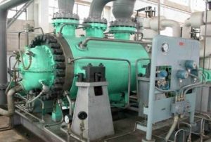
what is surge?
Dresser-Rand has been a leading designer and supplier of surge control systems for centrifugal and axial compressors for over thirty-five years.
Recent innovations in control technology have made it possible to supply surge control systems which are capable of coping with rapid flow fluctuations and process gas variations. Current surge control systems from Dresser-Rand Control Systems provide protection against surge with more efficient compressor operation, especially in process applications that involve variations in the gas mixture and temperature.
Several surge methods are in use today, each with its own approximations and consequent inaccuracies.
Operating the compressor safely in spite of these inaccuracies is usually accomplished by establishing the surge
controller flow set point based on the expected worst-case operating conditions. This worst-case flow set point may be excessive for normal operating conditions but is necessary in order to provide for safe operation at all expected operating conditions.
This worst-case setting approach can result in inefficient compressor operation caused by excess recycle or blow-off flow and wasted energy.
A more practical surge control method, which uses a Universal Performance Curve, has been developed and patented by Dresser-Rand. The Universal Performance Curve method offers several benefits when compared to traditional surge control methods. It provides extremely accurate surge control by defining the surge point over a wide range of process gas conditions. This method makes it possible to position the control line for optimum surge protection which eliminates unnecessary recycling and increases overall plant operating efficiency.
Compressor Surge and Measurement
Centrifugal and axial compressors will surge when forward flow through the compressor can no longer be maintained, due to an increase in pressure across the compressor, and a momentary flow reversal occurs. Once surge occurs, the reversal of flow reduces the discharge pressure or increases the suction pressure, thus allowing forward flow to resume again until the pressure rise again reaches the surge point.
This surge cycle will continue until some change is made in the process or compressor conditions.
A surge controller typically measures a function of pressure rise versus flow. The controller operates a surge
valve to maintain sufficient forward flow to prevent surge.
Surge Control Algorithm
Dresser-Rand’s method of accurately defining the surge point over a wide range of changing conditions makes it possible to set the control line for optimum surge protection without unnecessary re-cycling. This method automatically compensates for changes in molecular weight, temperature, compressibility, pressure and compressor rotor speed.
The system utilizes a characterization of compression ratio (Pd/Ps) versus compensated compressor inlet flow function (hs / Ps) ½ as control parameters. This algorithm allows for use of the Dresser-Rand surge control
system on most applications, resulting in minimized recycle or blow-off flow. This method reduces the initial cost
and simplifies engineering, testing, operation, and maintenance associated with the system when compared to alternative methods.
The input signals required to facilitate use of the surge control algorithm on centrifugal compressors are the
suction flow differential pressure, suction pressure and discharge pressure as indicated in Figure 1.
Surge Control Operation
Figure 2 illustrates the use of the universal surge control map. The compressor flow set point is provided by the control line. The location of the control line in comparison to the surge line depends on the slope of the speed lines of the map. The control line is positioned to the right of the surge line which provides a safety margin for the surge controller PI (Proportional & Integral) algorithm. The PI control loop is used to compare the control set point to the operating point of the compressor and provides an output to the surge valve to prevent the flow from decreasing below the control line. When a safe relationship between the control line and the surge line is determined, this relationship is configured into the surge controller.
Under normal operating conditions, PI control is used and surge control action is initiated at the control line by opening the surge valve as required to maintain forward flow through the compressor. This prevents a further shift of the operating point to the left towards surge.
In the case of rapid reductions in flow, such as process upsets, three additional controls are implemented.
First, a backup line, located between the control line and the surge line, is used. If the compressor operating point moves to the left of the control line and reaches the backup line, Dresser-Rand’s Closed Loop Step Logic will
quickly force the surge valve open as required to increase forward flow through the compressor.
Second, if the operating point of the compressor reaches the backup line a set number of times (i.e. 3), within a specified period of time (i.e. 5 minutes), the control set point will be shifted to the right via Dresser-Rand’s Set point Shift Logic.
Third, a variable proportional gain action has been added to the control loop to assist in stabilizing the process when rapid decreases in compressor flow are encountered.
Step Logic
The backup line is positioned between the surge line and the control line and provides a basis for additional control action. If the operating point of the compressor decreases to flow values less than those defined by the backup line, traditional PI control is enhanced by the Closed Loop Step Logic control function to facilitate rapid opening of the surge valve.
The output to the valve is forced to decrease in discrete, timed steps, thus opening the surge valve much quicker than possible with conventional PI control. Valve opening steps are initiated until the flow has moved to a safe level.
Compressor surge is avoided by this quick incremental control of the surge valve thus minimizing the effects of process upsets.
Set Point Shift
If the flow decreases to the backup line a predetermined number of times (adjustable) within a given time period (indicating a recurring problem) the surge control set point is shifted a percentage of full scale flow (i.e. 2%) in the direction of higher flow. This action establishes a larger margin of safety from the surge line. The flow set point continues to be shifted as necessary until the backup line crossings cease, or to a maximum of ten percent
greater than the control line value.
The intent of the set point shift is to prevent surge until the cause of the instability can be corrected. The shifted set point remains in effect until reset by the operator.
Floating Proportional Algorithm
In general, the controller needs to be slow for normal operating conditions, but fast when needed to protect
the compressor from surge. During rapid decreases in flow near the surge control line, Dresser-Rand uses a
Floating Proportional control algorithm to open the surge valve before the operating point reaches the
control line.
Normal PI control is resumed when the process upset has been stabilized.
Implementation
There are two methods of implementing the Dresser-Rand surge control algorithm.
The first method uses the DI-TRONICS® IV control system. This PLC (Programmable Logic Controller) based control system incorporates surge control as an integral part of the PLC program without the need for additional external hardware. Compressor inlet flow, suction pressure, and discharge pressure measurements are input directly into the system using standard PLC analog inputs. The tuning parameters are displayed and adjusted from an Operator Interface (OI) screen. Compressor curves, with the operating point, control line and back-up line are displayed on the Operator Interface monitor. The system parameters are trended and displayed on the Operator Interface monitor.
The second method utilizes a stand-alone controller and is offered for installations which do not require a PLC, or for those applications where the PLC used is not capable of providing adequate surge control.
Both systems utilize the Universal Performance Curve concept.
Field Devices and Process Designs
Compressor surge is a phenomenon which can occur very rapidly during upsets in process conditions. Proper surge control requires not only an appropriate control algorithm and a dedicated control strategy but, also specific attention to the field devices and process design.
Flow measuring devices should be located such that gas disturbances will be minimized (less noise), and designed for the full operating range of the compressor.
Transmitters should be located as close as possible to the source of measurement to minimize reaction time.
Surge valves should provide a full stroke response preferably within 1 second, but no more than 2 seconds.
The surge valve should be linear and should be sized in accordance with the compressor maps and expected operating conditions.
Since the effects of opening the surge valve are a decrease in compressor discharge pressure and/or an increase in suction pressure, to increase flow through the compressor, process and piping designers should minimize, as much as practical, the piping volume in the recycle path and the volume between the compressor and the discharge check valve.

