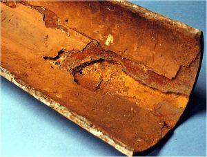
Before talking about corrosion in oil and gas facilities, we have to define some of the main sections of these facilities:
Gathering System and Manifolds Unit
– Gather the flowlines that convey the liquid and/or gaseous hydrocarbons coming from production wells.
– Send the product, by means of block valves and in safety conditions, on the production or test manifold to the treatment Units.
Separation Unit
– Separation tests and relevant measures.
– Carry out the production tests on the single wells.
– Analysis of oil phases, salted water and associated gas, separated under determinate pressure and temperature conditions;
– Effluents are sent to the relative treatment Units or flared.
Separation
that happens in Oil – Gas Separators : Separate the reservoir water and gaseous phase from oil by more separation stages, connected in cascade and working at decreasing pressures; – Convey separately the various phases to the relative treatment Units
Oil Stabilization Unit
– Dehydration / desalination of the crude:
– Separate the reservoir free-water emulsified with high viscosity crudes, by heating and suitable settlement times in proper equipment (gun barrel, desalter, heater treater).
– Wax removal.
– Stabilization:
– Stabilize the crude coming from primary treatment, at temperature and pressure required by transport and storage in accordance with sale specifications.
– Crude transfer to storage or export pipeline.
– Dehydration by di- or tri-ethtylene glycol absorption column.
– Gas dehydration by molecular sieves in alternative or after dehydration by glycol.
Gas Sweetening
– Assure the removal of acid fractions from a gaseous stream to reach the specification characteristics; the sweetening process involves the removal of CO2, H2S and mercaptanes.
– Sweetening can be carried out by one or two processes in series; in the case of two processes:
-the first provides for CO2 and H2S rough removal;
-the second is used to take the gas to specification values.
Furthermore, selective processes can be utilized for the single gases to be removed. Function can include, according to the reservoir gas characteristic, a sulfur recovery plant, a H2S flare to avoid atmospheric contamination.
Water Injection
– Supply high quantities of water, suitably treated, to the pressure required for injection into the reservoir in order to increase recovery of remaining oil.
Treatment includes:
– filtration (upstream and downstream of process);
– deaeration (to reduce oxygen to 0.05 ppm in order to reduce corrosion);
chemicals dosing in order to:
-neutralize the presence and development of biologic activities,
-inhibit formation of precipitates, inhibit corrosion phenomena;
-improve the performances of each single stage of water treatment.
Production Fluid Types
Mono-phase Hydrocarbon Systems
– Gas Hydrocarbons
– wet gas: gas below or close to the dew point: water and/or condensates are present or may develop.
– dry gas: gas is significantly above the dew point thus free from liquid phase
Liquid Hydrocarbons
– crude oil (and water)
– stabilized oil
– condensates (and water)
Multi-phase Hydrocarbon Systems
– Oil, gas (and water)
– Hydrocarbons: from the lighter (Methane CH4) – to the heavier (Decanes C10H20, Tridecanes etc.)
– Compounds as Asphaltenes and Paraffines, Resins etc.
– Water
– Carbon Dioxide (CO2)
– Hydrogen Sulphide (H2S)
– Sand / Solid Particles.
Water Associated with Production Fluids
– Water associated with the production fluid could have the following origin:
– Condensed Water: caused by condensation from wet gas hydrocarbons (due to pressure and/or temperature variations). Very low mineral content, low chlorides, low pH (typically 3 – 4)
– Formation (or production) Water: present in the reservoir and carried over together with the production fluid in oil and multiphase systems. It is characterized by higher pH (4 – 5.5) and high chlorides content (typically 10’000 – 100’000 mg/l) .
– The content of the production water is expressed as “water cut” that is the percentage of the water on the total liquid.
– During production the fluid in the reservoir is subjected to isothermal expansion which, in the case of wet gas can lead to condensation of gas in the reservoir initially gas monophase.
– Throughout the tubing, fluid is subjected to a polytrophic transformation (decrease of temperature and pressure from bottom hole to wellhead) which can give place to:
– gas phase formation in oil wells, when the bubble point pressure is reached,
– liquid phase (gas or light hydrocarbons) condensation in the case of retrograde condensation of gas wells.
Internal Corrosion Evaluation
– Hydrocarbon production wells are often accompanied by natural presence of carbonic acid (CO2) and hydrogen sulphide (H2S) in combination with mineralized water.
– Fluid from the reservoir is naturally free from oxygen.
– The characterization of the fluid corrosivity is mainly determined by the presence of CO2 and/or H2S, their amount and their relative ratio:
– the production fluid is classified “SOUR” if H2S is present and classified “SWEET” if it is not.
– fluid is called “CO2 –dominated” if the CO2/H2S > 200 and H2S dominated otherwise.
– Associated water amount (water cut), origin (formation or condensation), pH and chlorides content are also of major importance.
– WATER CUT (%)
– Water phase actual (in-situ) pH
– Water phase salinity (chlorides content mg/l)
– Water phase chemical composition
– CO2 CONTENT (molar fraction %)
– H2S CONTENT (molar fraction %)
– OPERATING CONDITIONS: Pressure / Temperature
– GAS OIL RATIO (GOR) at standard conditions
– FLOW RATES, FLOW VELOCITY and phase distribution (“flow pattern”)
– OTHER: Check for presence of SRB, Elemental Sulphur, Mercury, Solid Particle (Sand) or contamination with Oxygen.
– CO2 Corrosion
– Sulphide Stress Cracking (Sour Service) “SSC”
– Hydrogen Damage (Sour Service), “HIC, SOHIC, Blistering”
– Erosion Corrosion
– Galvanic (Bi-Metallic) Corrosion
– Microbiological Induced Corrosion, “MIC”
– Localized Corrosion (pitting, crevice).
There are two basic requirements for carbon steel to corrode:
– FIRST, LIQUID WATER MUST EXIST AS A FREE AND SEPARATE PHASE.
Water in oil as an emulsion will not cause corrosion.
– In oil system, water wetting is uncertain between 5% to 40% water. This can be a function of crude type and flow
regime.
– In wet gas systems, water wetting is expected due to water condensation.
– SECOND, LIQUID WATER MUST WET THE SURFACE OF CARBON STEEL EQUIPMENT. Therefore, gas-to-oil ratios, water cuts, flow effects and flow pattern are used as rules-of-thumb.
LIQUID WATER, WETTING THE METAL IS A NECESSARY CONDITION FOR CORROSION TO TAKE PLACE.
EXPECTED CORROSION FORMS
– Possible corrosion forms caused by produced fluids strictly depend on the metallic material in contact with the fluid.
– To assess the corrosivity of the produced fluids – and particularly concerning CO2 corrosion – reference is first made to carbon and low alloy steels as base case for material selection.
– For the most common O&G production fluids, the following forms of corrosion shall be anticipated and evaluated for candidate materials:
– CARBON AND LOW ALLOY STEELS
– CO2 corrosion – general and localized.
– Sulphide Stress Cracking, SSC
– Hydrogen Induced Cracking, HIC
– Erosion corrosion
– CORROSION RESISTANT ALLOYS (CRA)
– Localised – pitting and crevice – corrosion
– Sulphide Stress Cracking, SSC
– Chlorides Stress Corrosion Cracking, CSCC
Flow Pattern (multiphase system: oil/gas)
– If one considers gas-liquid mixtures flowing in a pipe, the two phases may distribute in a variety of “flow patterns”.
-The particular “pattern” depends mainly on flow rates, fluid properties and tube sizes.
-The evaluation of the prevalent “flow pattern” is important because it determines the effects of corrosion caused by the fluid.

